Taming POV-Ray - Part 2: Manipulating Objects
by G. Moran, 17 Mar 2024
This article covers the many ways to manipulate 3D objects in POV-Ray. By learning about 3D transformations and Constructive Solid Geometry (CSG), we can make complex models out of the basic shapes that POV-Ray provides.
Table of contents
Transformations in 3D
In the previous article we got familiar with the 3D objects available in POV-Ray and placed a few of them into a scene, now we're going to apply some 3D transformations on them, similar to the 2D transformations we did before.
Before we do any transformations though, let me mention a little detail about the 3D coordinate system that I skipped in the previous article... Remember when I said that if the positive x axis is going right and the positive y axis is going up, then the positive z axis will go into the screen? That is not always true; sometimes the positive z axis goes out of the screen!
You see, the 3D coordinate system can follow one of two "orientation systems"; the left hand system and the right hand system. To understand how those work, make an "L" shape with your hand:

Original image from Wikimedia Commons

Pretend that your thumb is the x axis and your index finger is the y axis, then align your hand to the screen so your x axis goes right and your y axis goes up... Now pretend that the z axis is coming out of your palm; if you were raising your left hand then your z axis will go into the screen, and if you were raising your right hand then your z axis will go out of the screen. That's all there is to it!
POV-Ray by default uses the left hand system, so this is what we will use. Switching to the right hand system is possible however it is outside the scope of this article.
We will do all 3D transformations directly in POV-Ray. Create a new scene with the following text:
/* 3D transformations scene */
#version 2.0
#include "colors.inc"

camera {location <3,5,-7> look_at <0,0,0>}
light_source {<9, 9, -9> color White}

plane {y, 0 pigment {checker color Gray color White}}

#declare Axis = union
{ cylinder {x*0,x*2,.1} cone {x*2,.2,x*3,0} }

object {Axis              pigment {color Red}}
object {Axis rotate z* 90 pigment {color Green}}
object {Axis rotate y*-90 pigment {color Blue}}
object {Axis rotate y*180 pigment {color Magenta}}
object {Axis rotate z*-90 pigment {color Yellow}}
object {Axis rotate y* 90 pigment {color Cyan}}
This will give us a boilerplate scene with a camera, light source, 2D checkerboard plane (grid), and colored axes.
Translation
Let's add a sphere at the origin with radius 1:
sphere {
    <0,0,0>, 1
    pigment {color Orange}
}

The sphere is halfway inside the checkerboard plane, so we're going to translate the sphere by 1 unit (the length of the radius) in the positive y direction. In other words, we're moving the sphere "up" by 1 unit so it's completely outside the plane... We're also going to translate the sphere by 2 units along x:
sphere {
    <0,0,0>, 1
    pigment {color Orange}
    translate <2,1,0>
}

What we did here was add the word translate followed by a 3D vector to our sphere {} block, where the vector contains how many units we're translating by in the x, y, and z axes. Since we're not doing any translation in the z axis, we wrote zero in the z component of the vector.
If you're confused just raise your left hand, make an "L" shape, and align it with the screen like you did before. The way your thumb, index, and palm are pointing is where positive translation will happen along the x, y, and z axes respectively.
Scaling
Now we're going to scale our sphere by 0.5, basically shrinking it to half size. But if we scale it while it's away from the origin then both its size and distance from the origin will scale, when we only want to scale the size relative to the sphere center... So we're going to do the same trick outlined in the 2D article; translate the object to the origin, scale it, then translate back to the original location.
We know that the sphere's center is currently at <2,1,0> so we first need to translate it to the origin:
sphere {
    <0,0,0>, 1
    pigment {color Orange}
    translate <2,1,0>

    translate <-2,-1,0> /* move to the origin */
}
Then we're going to scale the sphere by 0.5:
sphere {
    <0,0,0>, 1
    pigment {color Orange}
    translate <2,1,0>

    translate <-2,-1,0> /* move to the origin */
    scale 0.5           /* shrink to half size */
}

Then finally we're going to translate back to <2,1,0>:
sphere {
    <0,0,0>, 1
    pigment {color Orange}
    translate <2,1,0>

    translate <-2,-1,0> /* move to the origin */
    scale 0.5           /* shrink to half size */
    translate < 2, 1,0> /* move back */
}

Notice how the sphere, now shrunken, hovers above the plane instead of resting on top of it? That's because the center point of the sphere has not changed while its dimensions, including its height, has shrunk. To put it in numbers, the center remained at <2,1,0> before and after scaling, while the radius went from 1 to 0.5... If we wanted to keep the sphere exactly on top of the plane, we would have changed the last translation vector, specifically the y component, to account for the sphere's new size.
sphere {
    <0,0,0>, 1
    pigment {color Orange}
    translate <2,1,0>

    translate <-2,-1,0> /* move to the origin */
    scale 0.5           /* shrink to half size */
    translate <2,0.5,0> /* move back at new size */
}

Alternatively, we could model the sphere to be on top of the plane from the very beginning, so we would have the freedom to enlarge or shrink it without having to keep track of its y distance from the plane.
So far we have been scaling the sphere by a 1D factor, so the scaling happens across all 3 axes uniformly. What if we wanted to scale non-uniformly by different amounts in each axis? In that case we replace the 1D factor by a 3D factor:
sphere {
    <0,0,0>, 1
    pigment {color Orange}
    translate <2,1,0>

    translate <-2,-1,0> /* move to the origin */
    scale <1, 0.5, 1>   /* shrink to half height */
    translate <2,0.5,0> /* move back at new size */
}

As you can see, the sphere has been squashed. That's because we only scaled along the y axis by a factor of 0.5, with no scaling along the other axes. Recall from the 2D article that a scaling factor of 1 means no scaling, which is why the x and z components of the scaling vector are 1.
We can use non-uniform scaling to distort shapes in many ways:
sphere {
    <0,0,0>, 1
    pigment {color Orange}
    translate <2,1,0>

    translate <-2,-1,0> /* move to the origin */
    scale <1, 0.5, 2>   /* x0.5 height, x2 depth */
    translate <2,0.5,0> /* move back at new size */
}

Rotation
A sphere is too uniform to clearly showcase rotation, so let's add a cone extending from the origin 2 units along the y axis:
cone {
    <0,0,0>, 1, <0,2,0>, 0
    pigment {color Yellow}
}

Now we're going to rotate the cone so it points along the negative x axis instead of the y axis. In other words, we're making the cone point "left" instead of "up". To better understand what this looks like, here's a 2D view:

In 2D space rotation was done about the origin, but in 3D space rotation is done about the axes. Typically you would pick one axis at a time and rotate your object(s) about it, the way birds would rotate about a flag pole or lambs would rotate about a spit rod. In the case of the cone we only need to rotate about one axis; the z axis.
Now we have to determine the angle of rotation. By eye we can tell that this is an angle of 90 degrees, but is it positive or negative 90 degrees?...
Let's refer back to the left hand system introduced earlier; with your left hand make a "thumbs up" shape, then align your thumb so it's pointing along the z axis which we're rotating about. The direction your fingers curl is how positive rotation will happen about the axis, like so:

Original image from Wikimedia Commons

So we'll be rotating our cone by positive 90 degrees about the z axis:
cone {
    <0,0,0>, 1, <0,2,0>, 0
    pigment {color Yellow}
    rotate z* 90  /* rotate +90 deg about z */
}

Just like translate, the rotate keyword is followed by a 3D vector, in this case z (shorthand for <0,0,1>) multiplied by positive 90 degrees, resulting in <0,0,90>. That means rotate by 90 degrees about z, with no rotation about the other axes. I personally prefer to write z*90 than <0,0,90> for clarity.
Now let's say we want to rotate the cone further so it points along the negative z axis ("out of the screen"), this time we'll need to rotate about the y axis by 90 degrees. To determine the rotation sign, make a "thumbs up" shape with your left hand again and point it along the y axis; you'll find that we need to rotate 90 degrees opposite to the direction your fingers curl...
So we'll be rotating by negative 90 degrees about the y axis:
cone {
    <0,0,0>, 1, <0,2,0>, 0
    pigment {color Yellow}
    rotate z* 90  /* rotate +90 deg about z */
    rotate y*-90  /* rotate -90 deg about y */
}

The rule of thumb when it comes to rotation is that you always rotate about a single axis at a time to avoid any confusion. If you write rotate <180,90,45> then POV-Ray will rotate your object by 180 degrees about x, then by 90 degrees about y, then by 45 degrees about z, which may not be what you want.
Constructive Solid Geometry (CSG)
POV-Ray's basic shapes are nice and all, but we could create more elaborate shapes by manipulating multiple objects together. For example we could group two objects and transform them as one, or subtract one object from another, or intersect multiple objects... These operations are called Constructive Solid Geometry (CSG).
Here's a quick 2D visualizer of the CSG operations that POV-Ray supports:
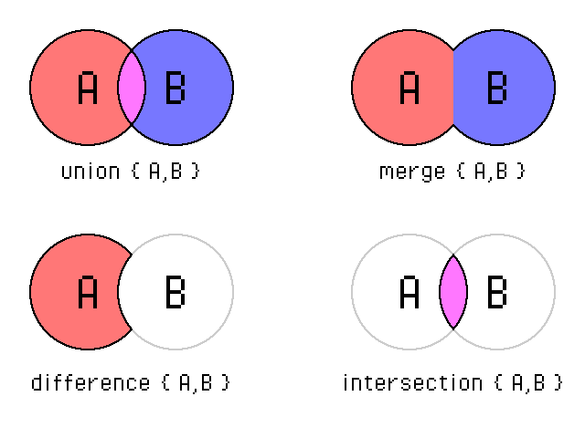
We will go over each of these operations in detail and apply them to different objects in POV-Ray, with each operation creating a new shape. We're also going to remove the colored axes to better see our objects.
Union
Union is the simplest CSG operation there is; it groups multiple objects together. Once grouped, the objects in the union are treated as one object...
Let's say we want to build a basic snowman with two spheres for the head and body, and add a white color to both spheres. In 2D view it would look something like this:

To group the two spheres, we enclose them in a union {} block then give the union a color:
union {
    sphere {<0,0.6,0>, 1}   /* snowman body */
    sphere {<0,2,0>, 0.6}   /* snowman head */
    pigment {color White}   /* make both white */
}

Note that specifying a color in the union block, or any CSG block, automatically applies said color to all the objects inside.
How about giving the snowman a hat?
Let's model one out of cylinders near the origin, then lift it up above the snowman's head and give it a nice golden color.
union {
    sphere {<0,0.6,0>, 1}   /* snowman body */
    sphere {<0,2,0>, 0.6}   /* snowman head */
    pigment {color White}   /* make both white */
}

union {
    cylinder {<0,0,0>, <0,0.1,0>, 0.9}  /* hat base */
    cylinder {<0,0,0>, <0,0.5,0>, 0.6}  /* hat top  */
    translate y*2.5                     /* place on head */
    pigment {color Gold}                /* make hat golden */
}

We now have two unions for the snowman and his hat, but what if we want to manipulate the snowman with his hat? Simple; we enclose the two unions in another union {} block:
union {
    union {         /* snowman */
        sphere {<0,0.6,0>, 1}
        sphere {<0,2,0>, 0.6}
        pigment {color White}
    }
    union {         /* hat */
        cylinder {<0,0,0>, <0,0.1,0>, 0.9}
        cylinder {<0,0,0>, <0,0.5,0>, 0.6}
        translate y*2.5
        pigment {color Gold}
    }
    translate z*-3  /* move them both */
}

CSG operations can be nested like this to create all sorts of combinations, we will see more examples of this later on.
Merge
Merge is almost exactly like Union but with one difference; if the objects overlap, the parts that are overlapping are "merged" together.
The best way to explain this is with an example; we're going to model a martini glass where the "neck" part overlaps both the head and base. Here's a 2D view with the overlapping areas in dark blue:

First let's model the glass as a union:
union {
    cone {<0,0,0>, 0.6, <0,0.3,0>, 0.2 open}  /* base */
    cylinder {<0,0,0>,  <0,2.5,0>, 0.2 open}  /* neck */
    cone {<0,1.5,0>, 0.2, <0,2.5,0>, 1 open}  /* head */
    pigment {color Cyan filter 0.5}   /* glass color  */
}

Here we added the keyword filter after the color to make it transparent, followed by a number indicating the transparency level. 0 is fully opaque and 1 is fully transparent, so this glass is half transparent.
Notice how the glass' neck, which overlaps the head and base, is fully visible?..
Now let's model the same glass as a merge:
merge {
    cone {<0,0,0>, 0.6, <0,0.3,0>, 0.2 open}  /* base */
    cylinder {<0,0,0>,  <0,2.5,0>, 0.2 open}  /* neck */
    cone {<0,1.5,0>, 0.2, <0,2.5,0>, 1 open}  /* head */
    pigment {color Cyan filter 0.5}   /* glass color  */
}

The overlaps are no longer visible, and the glass looks much more natural. All we did was replace union with merge, the geometry of the glass is exactly the same.
Difference
Difference is essentially subtracting one or more objects from an initial object.
To demonstrate this we're going to model a crescent shape, by subtracting one circle out of another. Here's a 2D view:

Let's start by creating the first circle as a cylinder:
/* first circle */
cylinder {
    <0,0,0>, <0,0.5,0>, 2
    pigment {color Magenta}
}

Then we will enclose the cylinder in a difference block and add another cylinder after it to create a hole. Pay attention to the ordering here; the shape we're starting with is added to the difference block first, and all following shapes are subtracted from it to create holes.
difference {
    /* first circle */
    cylinder { <0,0,0>, <0,0.5,0>, 2 }
    /* hole */
    cylinder { <1,0,0>, <1,0.5,0>, 2 }
    pigment {color Magenta}
}

Huh, that's strange... Where is the hole?
The hole is there, however it seems to not reach the top of the cylinder. That's because both the cylinder and the hole have the exact same height, so the area at the top is simultaneously "filled" and "empty". Same goes for the area at the bottom. Such areas are in an undefined state and may be rendered by the raytracer as filled, empty, or a mixture of both...
To eliminate those areas and get a proper crescent, we have to extend the shape of the hole above and below the cylinder so it completely removes the troublesome areas:
difference {
    /* first circle */
    cylinder { <0, 0,0>, <0,0.5,0>, 2 }
    /* extended hole */
    cylinder { <1,-1,0>, <1,  1,0>, 2 }
    pigment {color Magenta}
}

We can add more shapes to the difference block and each one will create another hole in the first shape, as long as there's overlap between them.
Intersection
Intersection is essentially the area common between two or more overlapping objects.
To demonstrate this we're going to model an eye shape by overlapping 2 circles:

Let's model this shape with 2 overlapping cylinders for circles, and enclose both in an intersection block. The ordering doesn't matter here, any order in an intersection block will achieve the same result.
intersection {
    /* first circle */
    cylinder { <0,0, 1>, <0,0.5, 1>, 2 }
    /* second circle */
    cylinder { <0,0,-1>, <0,0.5,-1>, 2 }
    pigment {color SlateBlue}
}

We can add more shapes to the intersection block and only the area that is overlapping and common between all shapes will be rendered.
CSG-compatible objects
CSG operations (other than union) only work on solid objects, meaning objects that are filled and have a clear "inside" and "outside". Spheres, boxes, cylinders, cones, and planes are solid. Triangles and triangulated surfaces such as bicubic patches are not solid, since they have no real thickness and hence have no "inside" nor an "outside".
In some cases it's possible to perform CSG operations between a triangulated surface and a solid object, but CSG operations purely between triangulated surfaces is invalid and will result in an error.
Note: Height fields are an exception to the above rule; despite being triangulated surfaces they can be used in CSG operations just like any solid object.
Declarations
Sometimes you'll want to render an object more than once, for that you have two options; either model the object over and over (tedious, error-prone, wastes space), or model the object only once and simply reference it multiple times. The latter option is made possible by the #declare keyword.
To declare any object, simply add #declare MyObject = before the object's block. This declaration stores the object in memory and gives it the name MyObject, without rendering it. To render the declared object, add object {MyObject ...} later into your scene.
To better illustrate this concept, we will create a scene containing the 3 pyramids of Giza. We will start by modeling a single pyramid like so:
/* extra light */
light_source {<0, 4, -8> color Gray}

/* pyramid shape */
difference {
    box {<-1,0,-1>, <1,1,1>}
    plane {-x-y, 0 translate  x}
    plane { x-y, 0 translate -x}
    plane {-z-y, 0 translate  z}
    plane { z-y, 0 translate -z}
    pigment {color Gold}
}

The pyramid's CSG code may look complex but the idea behind it is actually quite simple. We start with a box centered around the origin and 4 "wall" planes surrounding it, then we tilt each plane towards the box as if it's collpasing and remove the overlapping areas using difference. I added an additional light source to the scene so you can better see the shape.
Now we're going to declare this shape and give it a name; Pyramid. It's preferred to use names with Capital letters when declaring objects, but you can choose any name you like as long as it's not a POV-Ray keyword. The shape is modeled by one difference block, so we will first add #declare Pyramid = before the block to store it in memory, then we will reference the newly declared object using object {Pyramid} so it gets added to our scene and rendered:
/* store the pyramid shape in memory */
#declare Pyramid = difference {
    box {<-1,0,-1>, <1,1,1>}
    plane {-x-y, 0 translate  x}
    plane { x-y, 0 translate -x}
    plane {-z-y, 0 translate  z}
    plane { z-y, 0 translate -z}
    pigment {color Gold}
}

/* place the shape in the scene */
object {Pyramid}
If we wanted to store the pyramid in memory and not render it, all we have to do is comment out or remove the object {Pyramid} line.
Now that we have a pyramid in our scene, let's add two more by writing object {Pyramid} two more times then translating each one separately.
/* place 3 pyramids in the scene */
object {Pyramid translate  2*x}
object {Pyramid}
object {Pyramid translate -2*x}

Very good, however the pyramids are all the same size. Let's scale each pyramid independently before translating it. Note that the scaling here is done before the translation, while the pyramid is still centered around the origin.
/* place 3 different pyramids in the scene */
object {Pyramid scale 1.5 translate  3*x}
object {Pyramid}
object {Pyramid scale 0.5 translate -2*x}

That's more like it.
Declarations are a powerful tool that greatly facilitates scene writing. We can declare all sorts of POV-Ray data, not just objects. Here are some examples:
#declare Height = 12
#declare BrightBlue = color rgb <0.3, 0.5, 1.0>
#declare ChessTiles = pigment {
    checker color Black color White
}
We will see more declarations in the upcoming articles.
Include Files
Another powerful feature of POV-Ray is the ability to include files in other files. Since the last article we have been including a file named colors.inc at the top of our scenes, this file declares a large number of colors that we can reference directly by name. Having all colors declared in a separate file allows us to include it into multiple scenes, without having to manually declare the colors each time... Also, not only do we get to reuse code by keeping it in a separate file, we also get to keep our scene file focused and uncluttered. It's much easier to reason about a group of small clearly named files, than a single giant file with a wall of code inside.
A good convenient way to structure your scenes is as follows:
- Create one file for your scene, named
scene.povfor example. This is the main file that you will feed into POV-Ray to render. - Create separate files for declaring each (non-trivial) object you model;
obj1.inc,obj2.inc,obj3.inc...etc. - Include each object in your scene by adding
#include "obj1.inc"
#include "obj2.inc"
#include "obj3.inc"
and so on at the top of thescene.povfile. - Avoid including
*.incfiles in other*.incfiles, as that can easily lead to a network of includes that is hard to debug, or "circular includes" (file A includes file B, and file B includes file A) that crash POV-Ray.
Wrapping Up
Now you should know how to manipulate shapes using 3D transformations, combine shapes using CSG operations, declare objects, and include files in other files. In the next article we'll learn how to give our shapes colors and textures, until then feel free to play around with POV-Ray and practice what you learned.