Taming POV-Ray - Part 1: The Third Dimension
by G. Moran, 04 June 2022
POV-Ray (Persistence Of Vision Raytracer) is an ancient but powerful 3D graphics program. Originally developed in the late 1980s as DKBTrace before being "rebranded" at the turn of the decade, POV-Ray was the bona fide raytracer. It's free, open source, and runs on pretty much every type of computer, making it perfect for average Joes in the 1990s to create cool 3D images with. Today POV-Ray is still actively developed, now capable of producing modern photorealistic renders, but also "historic" ones like the renders of yore.
I'm writing this article as part of a series on how to use POV-Ray, so other 3D enthusiasts can get into it with ease and create beautiful "era appropriate" scenes. Don't worry if you're completely new to the world of 3D art, I wrote this series specifically for people like you. If you're not familiar with basic 2D geometry or could use a refresher, I strongly recommend reading part 0 of this series before reading this part.
Table of contents
- The Virtual Studio
- The Third Axis
- Writing Your First Scene
- Basic 3D Shapes
- More 3D Shapes
- Wrapping Up
The Virtual Studio

Imagine you're on a film set inside a studio; the place is large and completely dark, there are lights all around but they're all turned off, props are placed in various positions on set, and a camera is set up aiming at the props. You turn on the lights to illuminate the set, then you go over to the camera and snap a picture... 3D scenes are exactly like this; you have a vast three-dimensional world that's completely dark, and inside that world you place light sources, objects, and a camera that you can aim anywhere. When you "snap a picture" with the camera a 3D image is produced, the process of producing said 3D image is called "rendering", and the resulting 3D image itself is called a "rendered image" or simply a "render".
Putting together a film set is easy, but there's one problem; you're blind. You can't see where you're placing the props, lights or camera. The only thing you can see is the picture produced by the camera after you click the snap button... This is POV-Ray. You place items in your scene "blindly" by specifying their location in numbers, then you render your scene and get an image. You can then make adjustments to the numbers and render your scene again, and so on.
Sounds tedious? Maybe, but we'll work around it...
The Third Axis
So how do we create a 3D scene and place items into it using numbers? To answer this question we first need to recall the 2D coordinate system from the previous article. In brief:
- The 2D world is a grid of cells, where each cell is a square identical to every other cell. Cells are used as units for measuring position, distance, and scale.
- The center of our world is a point called the origin.
- The origin has 2 virtual rulers called axes coming out of it; the
xaxis and theyaxis. Each axis is positive on one side of the origin, and negative on the other side. - We denote the position of any point on the grid by a pair of numbers called coordinates in the form
(x, y). The coordinates tell us how far along thexandyaxes is a point from the origin. - There are many 2D objects such as points, lines, triangles, rectangles, circles, and Bézier curves.
- All objects can be transformed. There are 3 transformations; translation, rotation, and scaling. All transformations happen about the origin. We measure translation by a translation vector, rotation by an angle of degrees, and scaling by a factor.
Our current 2D grid, when drawn on a screen, has a positive x axis going right and a positive y axis going up. If we drew a third positive z axis on the same screen it will go into the screen. To show you what the 3 axes look like I made this 3D render:

Each axis is represented here by an arrow; the red arrow is the positive x axis going right, the green arrow is the positive y axis going up, and the blue arrow is the positive z axis going into the screen. The common point where all 3 arrows extend from is the origin.
Only the positive side of the axes is shown above, so here's another 3D render with the negative side of the axes added in different colors:

The magenta arrow is the negative x axis going left, the yellow arrow is the negative y axis going down, and the cyan arrow is the negative z axis going out of the screen. Now we can see the origin more clearly as all axes are coming out of it.
The renders above only show the axes though, where's the grid?.. When we added a third axis to our system, our 2D grid of squares became a 3D grid of cubes. Modeling such a grid is very cumbersome and will produce renders so full of lines that you'll barely be able to see anything else, so we're gonna model a simple 2D grid instead:

This 2D grid covers the x and z axes, it is different from our previous 2D grid which covered the x and y axes. We can see every value of both x and z on this grid, but only one value for y which is zero. So this grid is useful for measuring the width and depth of objects, but not their height. Also it only measures objects with a y coordinate close to zero, as any other y coordinate would be too far away from the grid... It's not perfect, but it'll do.
So far we've used general words like "right", "up", and "into the screen" to describe the directions of the axes, but these words only make sense if we're looking at our axes from a certain point of view. What if we "walked around" the vast 3D space and looked at our axes from a different point of view?

Zoinks! All the directions are mixed up, even though we're looking at the exact same axes!.. To avoid such confusion always refer to directions in terms of the axes, never use general words except in cases where it's applicable. For example it's fine to use the word "up" to refer to the positive y axis when designing a street scene with a fixed camera, but not when designing a space scene with stars and planets, which way is up then?
So let's standardize our system... The 3D coordinate system has 3 axes; an x axis, y axis, and z axis. All axes extend out of the origin and each axis has a positive part and a negative part. We denote the position of any point relative to the origin using an x coordinate, y coordinate, and z coordinate in the form (x, y, z), this form is called a vector. A 3D vector may be used to denote the coordinates of a point, a direction for translation, or a factor for scaling.
Now that we have a basic understanding of the three dimensional coordinate system, let's jump right into the deep end and create our very first (basic) POV-Ray scene! It will help cement the ideas discussed so far and make it easier to learn new ones.
Writing Your First Scene
Before we get into it, make sure you have POV-Ray downloaded and working. There are two ways to get POV-Ray:
- Download the latest version from the official POV-Ray website. A setup EXE is provided for Windows, and the full source code is available for other platforms here. There's also the source for older versions here.
- Download my personal copy of version 2.2 from this link. You'll get a ZIP archive containing static POV-Ray executables for Windows and Linux, as well as a handy
renderscript. Make sure you check theREADME.TXTfile first!
After downloading POV-Ray you should try rendering any of the bundled scene files with a .pov extension, if they render successfully you're good to go.
Scene Header
To create a POV-Ray scene start by creating an empty plain text file, name it bplate.pov, then open it in a plain text editor like Notepad and type the following:
/* boilerplate POV-Ray scene */

#version 2.0
#include "colors.inc"
The line /* ... */ is a comment block, or more simply a comment. Comments are written in POV files mainly to communicate information to the human reader in plain English, so they are ignored by the program when it's processing the file. In this comment block we wrote a short description of our scene.
Comment blocks of the form /* ... */ can be single line or multi-line, starting at a /* and ending at the first */ that follows, wherever that may be. There's also an alternative form purely for single line comments, starting at a // and ending at the end of the line.
The #version line specifies the version of POV-Ray we're writing this scene for. We wrote 2.0 here as the minimum POV-Ray version required to render this scene is 2.0, but any later version will do just fine.
The #include line tells POV-Ray when processing our file to include the contents of another file here, as if this #include line was replaced by all the code in the other file... Here we're including a file named colors.inc, this file comes with POV-Ray and provides us with named colors that we can use in our scene. You can find the file inside the include/ folder.
Unfortunately POV-Ray by default doesn't look for included files in the include/ folder (or any folder, really) when rendering, so I wrote a handy render script that takes care of that for you. You can find the script bundled with my copy of POV-Ray 2.2, linked above.
Camera and Lights
Time to start setting up our scene by adding a camera and lights:
camera {
    location  <3,5,-7>
    look_at   <0,0,0>
}
light_source {<9, 9, -9> color White}
The camera {} block controls our virtual camera, here we specified its location and the point it's looking at. Each of these 2 points is denoted using a 3D vector (x, y, z) as discussed earlier, but enclosed in angled brackets following the POV-Ray code syntax, becoming <x, y, z>.
The light_source {} block controls a single light source illuminating our scene, here we specified its location and brightness. The location is denoted using a vector, while the brightness is represented by a color; the brighter the color the brighter the light, and vice-versa... For example a white light source is fully bright, a gray light source is dimmed, and a black light source has no brightness (i.e. is turned off). Light colors can be non-grayscale too; for example a bright red light will have a red tint, while a dark red light will have the same tint but will be dimmer.
What we wrote so far is essential for any scene, but we can't do any rendering until we add some objects...
Basic 3D Shapes
Cameras and lights don't count as "real" objects; they are not visible in our scene and can't be rendered on their own. To create objects we need to use some of POV-Ray's basic shapes.
Plane
Let's add the 2D grid we saw before as our floor:
plane {
    y, 0
    pigment {
        checker color Gray color White
    }
}
The plane {} block describes an infinite flat surface called a plane. Depending on its orientation, a plane can be a wall, ceiling, or floor. The plane described in the code above is a floor, its orientation is denoted by the line y, 0 which is a strange notation, so what does it mean?..
Imagine any plane; which axis is pointing straight "out" of its surface?
If we look at the floor plane rendered above we'll see the y axis "pointing out" of it, so we write y to denote the plane's orientation. Then we write how many units to move the plane along our axis away from the origin, in this case 0 as we want the plane exactly at the origin. We can replace y with other signed letters for the other axes, for example -y for a ceiling plane, or x and -x for wall planes, or -z for a back plane...etc.
Writing y is shorthand for the <0, 1, 0> vector, similarly there's x for the <1, 0, 0> vector and z for the <0, 0, 1> vector. These are direction vectors, because they're describing the direction of the axes. So when denoting a plane's orientation we're actually specifying the direction that's pointing straight "out" of the plane's surface. It can be the direction of an axis, or it can be any direction like <2, 1, 0>.
The pigment {} block describes the general color(s) of an object, in this case the object is the floor plane. A pigment can be a single color or a pattern of multiple colors, this floor plane for example has a checker (checkerboard) pattern in gray and white.
We now have at least one object in our scene, so let's render it:

Cylinders and Cones
The plane looks good but we could use some visible axes to guide us. Let's start by modeling the positive x axis:
/* red +x axis */
cylinder {
    <0,0,0>, <2,0,0>, 0.1
    pigment {color Red}
}
cone {
    <2,0,0>, 0.2, <3,0,0>, 0.0
    pigment {color Red}
}

The axis here is modeled as a red arrow, that is made up of one cylinder for the arrow shaft and one cone for the arrowhead.
The cylinder {} block describes a cylinder like a tube or a pipe, by specifying the point where it begins, the point where it ends, and the radius across the whole cylinder. We can also add the keyword open to make a hollow cylinder with open ends. Points are denoted using vectors as usual, and the radius is a single number representing how "thick" the cylinder is. The cylinder here has a small radius of 0.1 units, it begins at the origin <0, 0, 0>, then extends 2 units along the x axis at <2, 0, 0>, then ends.
The cone {} block is similar to the cylinder {} block, except there's a different radius for the start and end points. We first specify the start point and its radius, then we specify the end point and its radius, then the optional open keyword. The cone here begins where the cylinder ends at <2, 0, 0> with a radius of 0.2 units, then extends 1 unit along the x axis at <3, 0, 0>, then ends with a radius of zero (the pointy end of the cone).
We repeated the pigment {color Red} line twice to give the cylinder and cone a color, but can we achieve the same result without repetition? Yes of course:
/* red +x axis */
union {
    cylinder  {<0,0,0>, <2,0,0>, 0.1}
    cone      {<2,0,0>, 0.2, <3,0,0>, 0.0}
    pigment   {color Red}
}
This is called a union {} block, which groups several objects together and assigns them a common property such as a pigment. Here we added the cylinder and cone to a union so we can assign them both a red color with one line. Pretty convenient, right?
Let's model the positive y axis as a green arrow and the positive z axis as a blue arrow, then render our scene to see all three positive axes together:
/* green +y axis */
union {
    cylinder  {<0,0,0>, <0,2,0>, 0.1}
    cone      {<0,2,0>, 0.2, <0,3,0>, 0.0}
    pigment {color Green}
}

/* blue +z axis */
union {
    cylinder  {<0,0,0>, <0,0,2>, 0.1}
    cone      {<0,0,2>, 0.2, <0,0,3>, 0.0}
    pigment   {color Blue}
}

We can't forget about the negative part of the axes! Here's the negative x axis in magenta, the negative y axis in yellow, and the negative z axis in cyan:
/* magenta -x axis */
union {
    cylinder  {<0,0,0>, <-2,0,0>, 0.1}
    cone      {<-2,0,0>, 0.2, <-3,0,0>, 0.0}
    pigment   {color Magenta}
}

/* yellow -y axis */
union {
    cylinder  {<0,0,0>, <0,-2,0>, 0.1}
    cone      {<0,-2,0>, 0.2, <0,-3,0>, 0.0}
    pigment   {color Yellow}
}

/* cyan -z axis */
union {
    cylinder  {<0,0,0>, <0,0,-2>, 0.1}
    cone      {<0,0,-2>, 0.2, <0,0,-3>, 0.0}
    pigment   {color Cyan}
}
Our basic scene now has a 2D grid in the form of a plane, along with axes modeled using colored cylinders and cones. This is good "boilerplate" for building more complex scenes while having visible guides at all times for measurements and perspective... Remember, you can remove an object from a scene any time by simply surrounding its code with a comment block /* ... */ instead of deleting the code entirely. Comments are always ignored when processing a file.
Let's see what other basic shapes POV-Ray has for us...
Sphere
A sphere is like a ball, a very common shape in the raytracing world. Let's add one:
sphere {
    <1.5, 0.5, 1.5>, 0.5
    pigment {color Orange}
}

The sphere {} block contains a location vector for the sphere center, and a single value for the sphere radius. This sphere is centered at <1.5, 0.5, 1.5> and has a radius of 0.5, it looks like it's resting on top of our plane.
Box
A box is like a cube or a cuboid. Let's add one:
box {
    <-3,0,0>, <-4,2,-1>
    pigment {color Yellow}
}

The box {} block contains two location vectors for two points that are at opposite ends of the shape, they are denoted very similarly to the way we denoted 2D rectangles in the previous article. This box has one corner at <-3, 0, 0> and another corner completely opposite to it at <-4, 2, -1>.
Torus
A torus is like a donut or a ring. Let's add one:
torus {
    1, 0.2
    pigment {color Yellow}
}

The torus {} block contains only 2 numbers; a major radius and a minor radius. To understand what those are we need to imagine a torus as a plain wedding ring; the major radius enlarges or shrinks the empty middle area of the ring so it matches the thickness of your finger, while the minor radius increases or decreases the thickness of the metallic area... If you're confused, check this 2D view:

A torus is always created at the origin as if it's surrounding the y axis, we will learn later on how to transform it and move it around.
More 3D Shapes
There are many other shapes in POV-Ray, some are less used than others. I'm going to briefly cover the most noteworthy ones here for completion's sake... You can find a complete description of every shape in the POV-Ray manual.
Triangle and Smooth Triangle

Original 3D model from Blend Swap [POV source]
Triangles in POV-Ray are thin 2D shapes that have no real thickness, they are positioned in large groups with different orientations to represent a complex 3D shape. Such shapes are called triangulated 3D models because they're made up purely of triangles... Typically you don't write the code for each triangle by hand, instead you use a dedicated graphical 3D modeling program to create a model, then let the program generate a list of triangles for you which you can then import into POV-Ray.
Bicubic Patch
The bicubic Bézier patch is the 3D version of the cubic Bézier curve, it's like a thin sheet of paper that can be curved in many ways. Generally it's easier and more efficient to represent a curved surface using bicubic patches rather than triangles, for example the Utah Teapot was originally modeled using cubic Bézier curves converted to bicubic Bézier patches.
You could manually write the code for a bicubic patch when modeling a simple curved surface, but for more complex shapes it's better to generate bicubic patches using a dedicated graphical 3D modeling program, just like with triangles.
Fun fact: Behind the scenes, POV-Ray triangulates all bicubic patches before rendering them. Meaning each patch is converted to a set of triangles before being rendered.
Blob
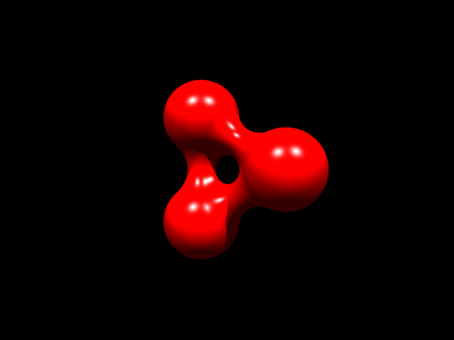
A blob is a special shape created by positioning multiple sphere-like shapes in a way that they "blend" with each other, creating an organic-looking shape. They're a bit tedious to model by hand so it's better to generate them using a dedicated graphical 3D modeling program.
Height Field

Height field using maps generated by POV-Ray [POV source]
A height field is a triangulated 3D model generated from a 2D image. The way it works is by taking a grayscale 2D image and converting (roughly) every pixel into one or more triangles at a certain height in 3D space depending on the brightness of the pixel. Height fields are commonly used to model mountains and hills, and there are dedicated "terrain generator" programs to create them.
The 2D image used to create a height field is called a height map. Typically you'd use a dedicated program to create a height map, but you can (indirectly) create one using POV-Ray! The manual outlines one way to do that.
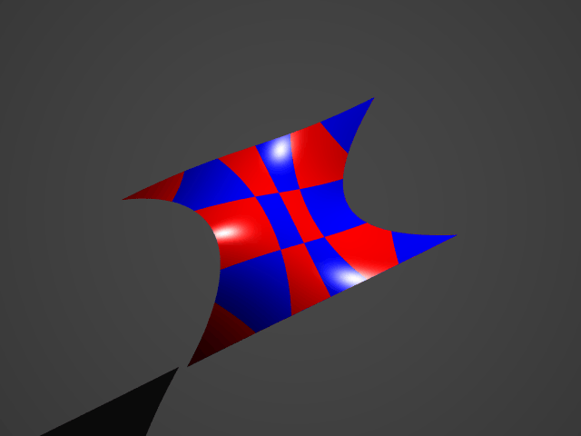
Quadric, Cubic, Quartic, and Poly

A Heart surface and multiple Tooth surfaces [POV source]
A polynomial surface (which can be quadratic, cubic, quartic or any other order) is a special shape that the user can model purely using mathematical formulae like this or this. You can find a list of known polynomial 3D surfaces on this page.
Side note: Most basic POV-Ray shapes (e.g. spheres, cylinders, torii) are actually polynomial 3D surfaces.
Wrapping Up
You should now know what is the 3D coordinate system, what are the common 3D shapes and how to use them in POV-Ray. In the next article we'll learn how to transform and manipulate 3D shapes, until then feel free to play around with POV-Ray and practice what you learned.
Here's a cheat sheet for the most commonly used POV-Ray shapes:
